The Quantum Syncro is equipped with a dual circuit brake system which is divided into a front axle circuit and a rear axle circuit.
The brake pressure regulator regulates brake pressure to the rear circuit in proportion to the front circuit.
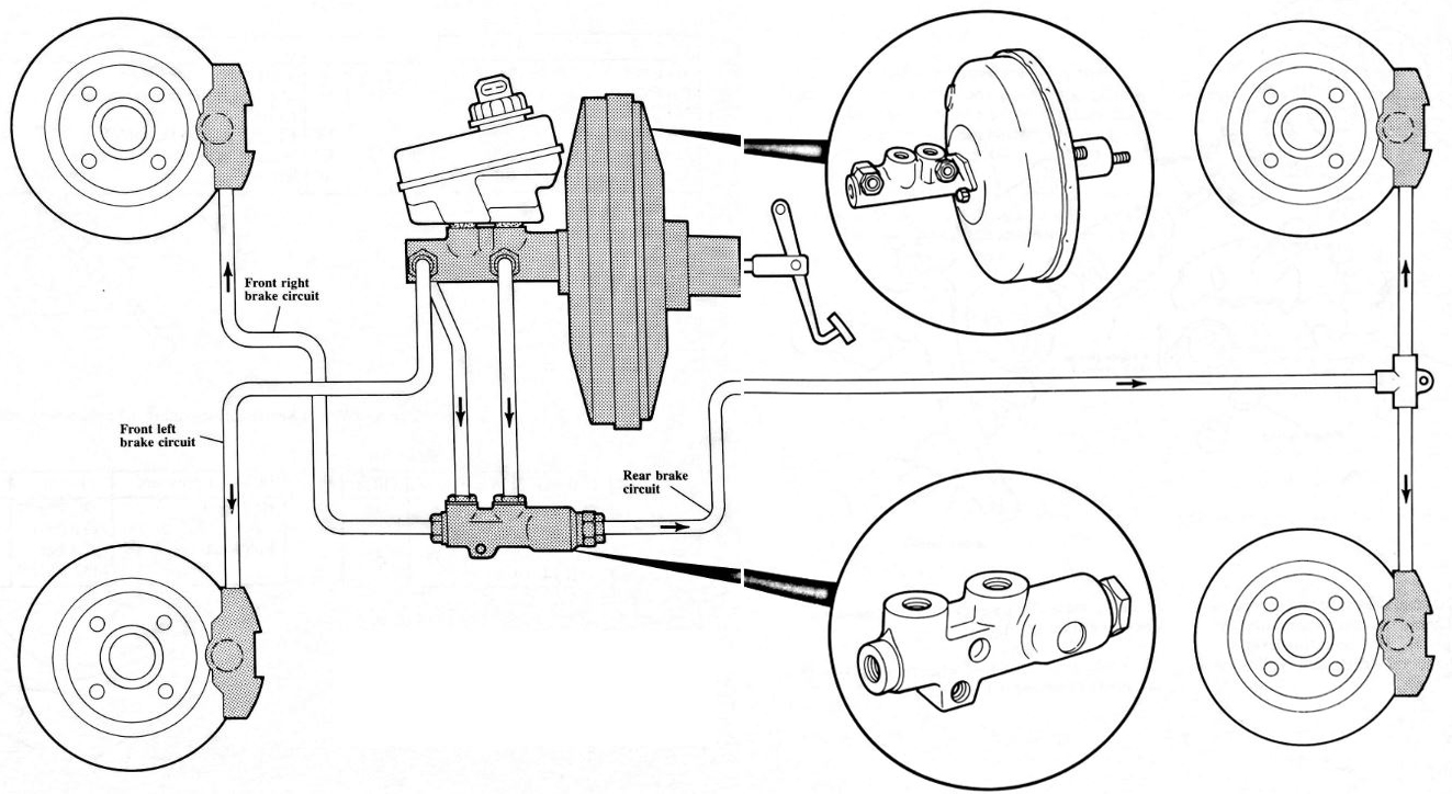 A 10″ diameter power brake booster with integrated master cylinder is lighter and more compact and produces a high degree of power assist.
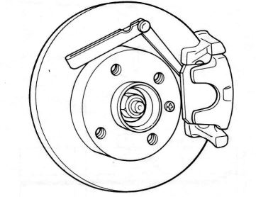
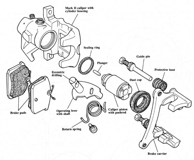 The rear Mark II disc brake caliper incorporates a self-adjusting handbrake mechanism directly into the caliper piston. The operating lever is actuated by the handbrake cable and applies the brake by means of an eccentric drilling in the operating lever shaft.
The brake pads on all four wheels of the Syncro are made of asbestos free material.
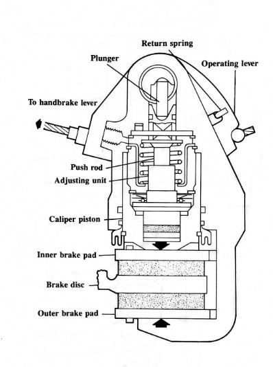 When the handbrake lever is pulled, the operating lever moves and pushes the plunger against the pushrod. The pushrod forces the caliper piston into contact with the inner brake pad.
When the pad contacts the brake disc, the plunger pushes against the pad housing and draws the outer brake pad into contact with the other side of the brake disc.
 The self-adjusting mechanism for the handbrake compensates for the change in pad to disc clearance that occurs as the pads wear.
All the components of the self-adjusting mechanism are incorporated in the caliper housing.
When the caliper piston moves, the adjusting nut is momentarily released from its conical seat on the inside of the piston. As it lifts, it is rotated by the thread on the push rod. The push rod itself is kept from rotating by the retaining plate.
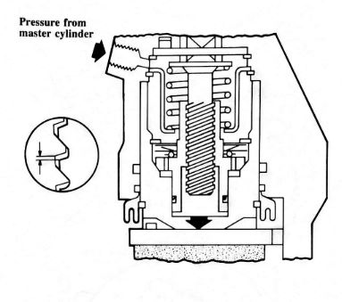 When pressure from the master cylinder moves the caliper piston and brake pad into contact with the brake disc, the adjuster nut is carried along due to spring pressure on the axial bearing. Once the distance between the pad and the disc has been taken up, the adjusting nut is released from its conical seat.
If enough brake pad wear has occurred so that the adjuster threads contact the threads on the push rod, as shown, the adjuster is rotated by the steep angle of the threads on the pushrod. This process keeps the handbrake in constant adjustment.
 As hydraulic pressure increases, the force exerted on the adjusting nut surface area increases and the adjusting nut is forced back onto the conical seat and can no longer rotate. The push rod now moves down together with the adjusting nut.
 The minimum allowable thickness of the brake pads is 7mm. When new rear pads are installed, the basic setting of the self-adjusting mechanism will have to be readjusted.
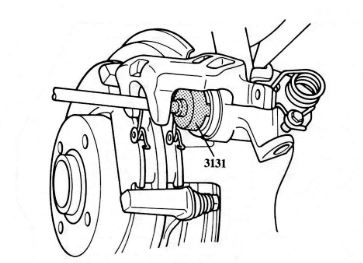
With the handbrake cable removed, the caliper piston can be threaded into the caliper with tool 3131.
 Once new pads are installed, a clearance of 1 mm must exist between the brake pad and the brake disc. This is so that a gap of 0.4mm is maintained at the adjuster nut inside the caliper piston to provide correct self-adjuster operation.
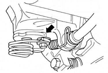 When the handbrake cable is reinstalled it should be tightened until the adjustment lever is lifted off its stop, no more than 1mm (arrow).
The adjustment of the cables should be checked whenever the handbrake cables, brake calipers, brake pads and brake discs are renewed.
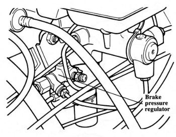
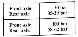
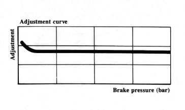
The brake pressure regulator is located below the power brake booster. It reduces brake pressure to the rear circuit to prevent the rear brakes from locking.
 This chart shows the regulation of brake pressure to the rear brakes. The regulator is preset and is not adjustable.
To test the operation of the pressure regulator:
- Lift vehicle and connect gauge VW1310 to left front and left rear brake calipers.
- Apply pressure to brake pedal and compare pressure readings to this chart.
- If out of specification, replace pressure regulator and re-test.