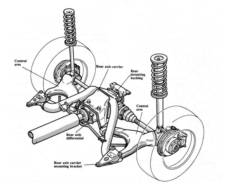
 The rear axle and suspension are a totally new design, featuring diagonal semi-trailing control arms. The rear axle carrier is bolted directly to the rear axle differential to form a single rigid unit.
The front of the axle carrier is attached to mounting brackets by two bonded rubber bushings. The brackets are then bolted to the body.
At the rear, the final drive is attached to the body crossmember by a single bonded rubber bushing.
The rear suspension struts have been designed with new springs and dampening rates to match the new rear suspension.
 As with all Quantum models, the Syncro uses the unique track correcting rear suspension.
The bushings that attach the rear axle carrier pivot, thus countering the steering effect of the rear axle.
During cornering, when the rear axle is subjected to lateral forces, the bushings deflect to minimize toe changes at the rear wheels.
The entire assembly moves in an arc with the rear differential bushing as the center point.
The two front mounting bushings are a two piece design. They are shaped to allow two air gaps.
During replacement, these bushings must be carefully installed because of their importance to the operation of the track correcting feature.
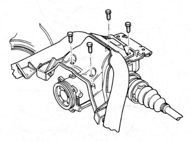
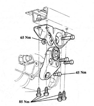
 Each side of the axle carrier itself is bolted to a bracket which is then bolted to the body. The three holes in each mounting bracket are elongated to allow for toe adjustments to the rear axle assembly.
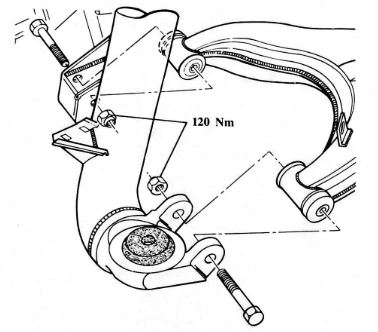
When removing the axle carrier, the mounting brackets need not be removed from the body. The axle carrier should be unbolted at the bonded rubber bushings. This will maintain rearwheel alignment after reassembly.
 The rear axle differential is bolted to the rear axle carrier. If the rear axle carrier has to be removed, the rear axle differential will have to be removed with it, and separated afterwards. During removal of the rear axle carrier, the control arms can remain attached to the struts.
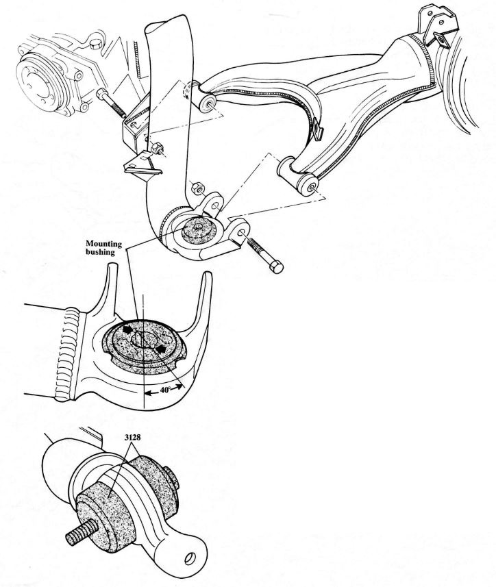 For proper operation of the rear axle, it is imperative that the bushings be positioned properly during assembly of the bushings.
The two centering grooves (arrows) must point outward 40deg as seen from the longitudinal centerline of the vehicle.
When replacing the bushings,special tool 3128 is used to pull each half of the bushing in separately.
The track correcting feature of the rear axle relies on a central pivot point for the suspension.
There is a single rubber bushing at the rear of the differential to provide this function.
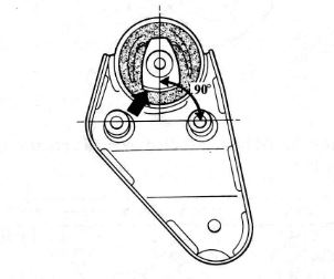 During replacement of this bushing, the wider side of the metal center piece (arrow) must be at right angles (90deg) to the two threaded sleeves so that the track correcting action of the rear axle is not adversely affected.
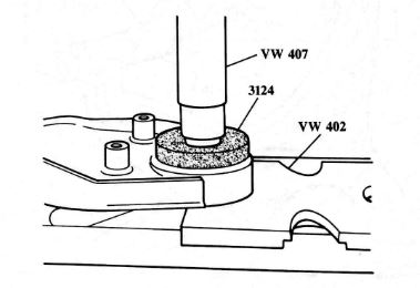 In the event that replacement of this bushing is required, special tool 3124 has been developed. It is used to press the bushing out and in.
 The rear suspension control arms are all new and are attached to the rear axle carrier with bonded rubber bushings.
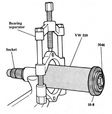 If the bushings need to be replaced, they can be removed using the bearing separator as shown,
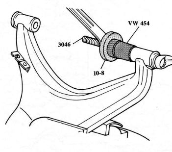 They should be reinstalled by pulling them into position.
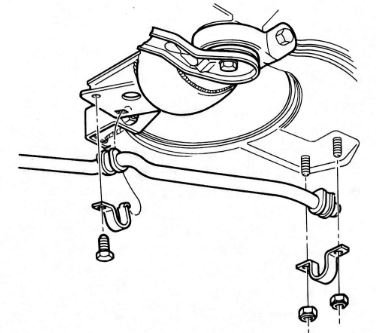 The stabilizer bar is mounted to the rear axle carrier with two bonded rubber bushings, and to the control arms with one bushing on each arm.