
The injection pump driveshaft turns the vane pump, cam plate and distributor plunger as a unit.
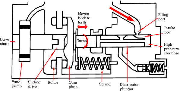
Springs hold the cam plate and distributor plunger against four rollers allowing the plunger to move back and forth as well as turn.
Whenever an intake port on the plunger is in line with the filling port in the pump body, fuel from the vane pump fills the high pressure chamber. The cam plate pushes the plunger to “squeeze” the fuel in the high pressure chamber to about 1800 PSI.
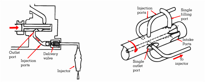 [ezcol_1half]As the plunger continues to turn, the outlet port lines up with the injection ports in the pump body.
The delivery valve opens under pressure and high pressure fuel is supplied to the injector.[/ezcol_1half] [ezcol_1half_end]The ports in the pump are arranged so that the injectors receive fuel in the cylinder firing sequence.[/ezcol_1half_end]
The amount of fuel injected is determined by the injection cut-off point. The injection cut-off point varies according to the engine speed and engine load.
The injection cut-off point is controlled by the metering sleeve on the distributor plunger.
The metering sleeve covers and uncovers a relief port in the plunger – uncovering the relief port stops injection.
The 4 diagrams below show the application of fuel metering over the entire speed range covering: starting, idle, part load, and full load.
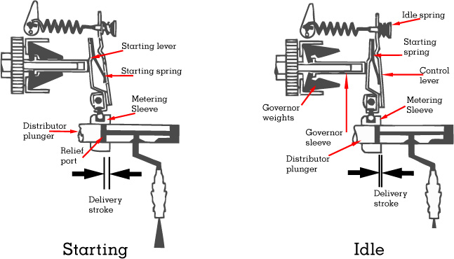 [ezcol_1half]When the engine is not running, the starting spring presses the starting lever to the left so that the metering sleeve moves to the right.
The distributor plunger must move further to expose the relief port.
Injection lasts longer so that more fuel is supplied during starting.[/ezcol_1half] [ezcol_1half_end]At idle speed the weights in the centrifugal governor are partially expanded so that the governor sleeve moves to the right. The starting lever pushes against the control lever so that the metering sleeve moves to
the left.
The distributor plunger now moves less to expose the relief port.
Injection lasts a shorter time so that less fuel is supplied at idle.[/ezcol_1half_end]
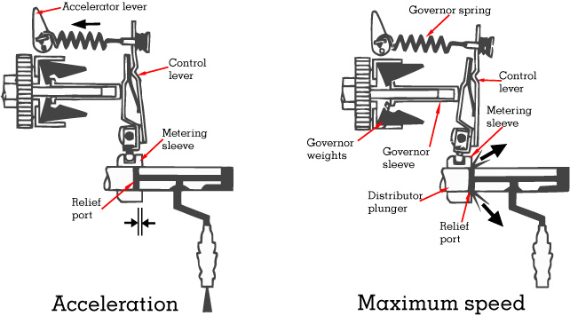 [ezcol_1half]During acceleration, the control lever is pulled to the left by the accelerator lever.
The metering sleeve is moved to the right so that more fuel is injected before the
relief port is uncovered.
Engine speed increases until the movement of the governor “neutralizes” the effect of
the pedal linkage.[/ezcol_1half] [ezcol_1half_end]With the accelerator lever at “full load”, engine speed increases to maximum RPM
(about 5400).
The governor weights are now stretching the governor spring and the control lever
moves to the right.
The metering sleeve moves to the left and uncovers the relief port at the beginning of
the distribution plunger stroke. Therefore there is LESS fuel injected and top speed
is limited.[/ezcol_1half_end]