
Installation and connection of the Power Pack box
THE POWER PACK BOX IS SUPPLIED ALREADY ASSEMBLED ON THE BATTERY SUPPORT (WITH BATTERY) . FOR A CORRECT INSTALLATION FOLLOW THE UNDER SHOWN INSTRUCTIONS.
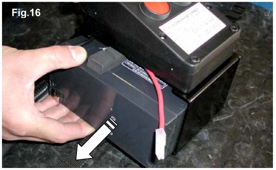 1. Extract the battery from the support after having unlaced the battery strap.
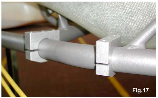 2. Position the support clamps on the outside rail (brake side) at the height of the seat.
NOTE: DIFFERENT CLAMPS ARE AVAILABLE DEPENDING ON THE DIAMETER OF THE TUBE ON THE CHASSIS.
FIX THE CLAMPS BY HAND WITH 2 SCREWS M6 X 25
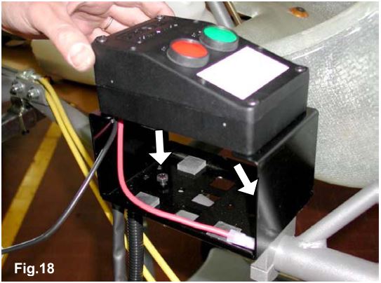 3. POSITION THE BATTERY SUPPORT BOX ON THE CLAMPS MATCHING THE ATTACHMENT HOLES (SEE FIG. 18).
FIX THE BOX WITH TWO SCREWS M6 X 10. MOVE THE BOX WITH THE 2 CLAMPS TO THE MOST SUITABLE POSITION.
TORQUE THE M6 SCREWS TO 8-10 Mn (70-90 in-lb)
 4. Insert the battery strap.
5. INSERT THE BATTERY WITH TERMINALS TOWARDS THE OUTSIDE (SEE FIG. 20).
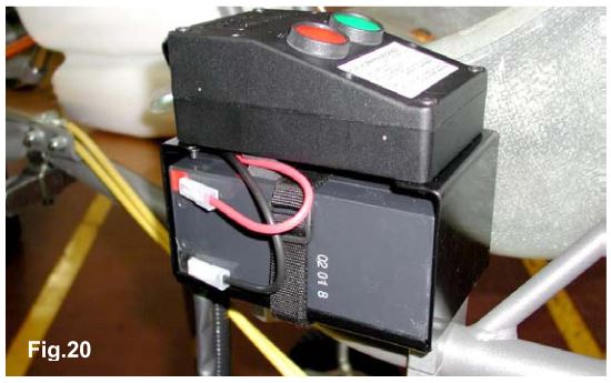 CONNECT THE BATTERY TERMINALS.
SUGGESTION: NEVER CONNECT THE BATTERY UNTIL YOU ARE READY TO START THE ENGINE. SEAL THE BATTERY TERMINALS WITH PLASTIC TAPE TO AVOID THAT EVENTUAL VIBRATIONS MIGHT DISCONNECT THE TERMINALS.
ATTENTION: PAY ATTENTION NOT TO SHORT CIRCUIT THE BATTERY TERMINALS AS BATTERY COULD BE DAMAGED BEYOND REPAIR.
Ground the Power Pack
Inadequate grounding of the Power Pack box could damage the box beyond repair. Make sure to carefully follow the following instructions.
 1. Remove the screw from the seat support (located underneath the seat)
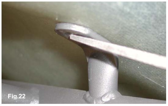 2. FILE THE PAINTING ON THE SEAT SUPPORT UP TO BARE METAL (SEE FIG.22).
ATTENTION: THIS OPERATION IS EXTREMELY IMPORTANT AS AN UNCERTAIN GROUNDING COULD DAMAGE THE POWER PACK BOX BEYOND REPAIR.
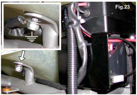 3. INSERT THE BOX GROUND CABLE EYELET ON THE SCREW AND TIGHTEN THE SCREW (SEE FIG. 23)
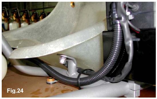 4. Position the harness from the power pack box along the central rail, underneath the seat, and tighten with plastic clamps.
Attention: Never let the harness get in touch with the ground or rotating parts as it could be damaged beyond repair.
Electrical connections on the engine
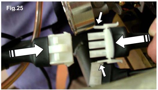 1. CONNECT THE TERMINALS (3 AND 4 WAYS) ON THE HARNESS FROM THE POWER PACK BOX WITH THE TERMINALS ON THE CABLES FROM THE IGNITION (SEE FIG. 25/26).
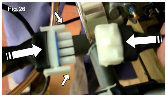 ATTENTION: MAKE SURE THAT THE FIXING TONGUES ARE PROPERLY INSERTED TO GUARANTEE THE BEST POSSIBLE CONNECTION OF THE TERMINALS.
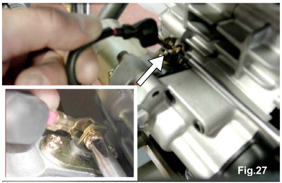 2. CONNECT THE CABLE (RED) FROM THE POWER PACK BOX TO THE ELECTRIC STARTER (USE THE SCREW ALREADY INSTALLED ON THE CABLE) (SEE FIG. 27).
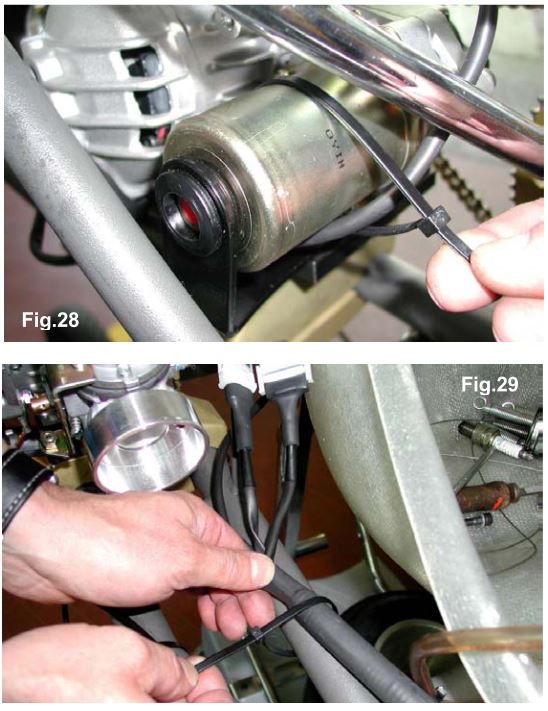 3. FIX THE ELECTRIC STARTER AND THE CABLE (SEE FIG. 28) AND COMPLETE THE FIXING OF THE HARNESS (SEE FIG. 29).
ATTENTION : NEVER LET THE HARNESS GET IN TOUCH WITH THE GROUND OR WITH A ROTATING PART AS IT COULD BE DAMAGED BEYOND REPAIR.
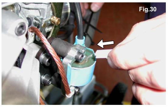 4. Connect the coil cable from the power pack to the terminal on the coil.
Suggestion: Seal the terminal on the coil with plastic tape to avoid that eventual vibrations might disconnect the terminal.
5. REMOVE THE SIDE BUMPER ON THE CHASSIS, ENGINE SIDE (IF NOT REMOVED YET).
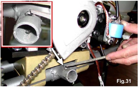 6. FILE THE PAINTING ON THE SLEEVE TO BARE METAL (SEE FIG. 31).
ATTENTION: THIS OPERATION IS EXTREMELY IMPORTANT, AS AN UNCERTAIN GROUNDING COULD DAMAGE THE IGNITION BEYOND REPAIR.
 7. INSTALL THE SIDE PLASTIC BODY AND CONNECT THE GROUND CABLE FROM THE CLUTCH COVER TO THE CHASSIS BY TIGHTENING THE FIXING SCREW (SEE FIG. 32).
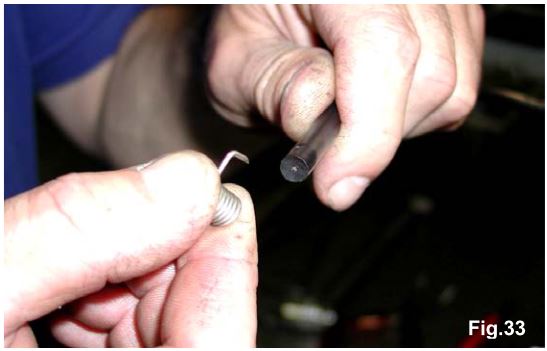 8. PUNCTURE THE INSULATING MATERIAL ON THE H.T. CABLE WITH THE END OF THE CAP SPRING SO THAT THE SPRING IS IN SURE CONTACT WITH THE INTERNAL WIRE (SEE FIG. 33).
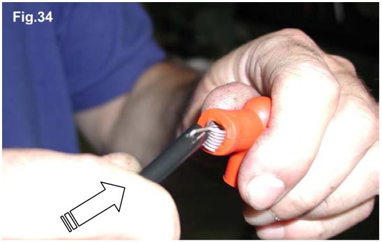 9. INSERT THE SPARK PLUG CAP ON THE SPRING (SEE FIG. 34). INSTALL THE SPARK PLUG AND THE CAP OVER THE SPARK PLUG.
- INSTALL THE SPARK PLUG
- INSTALL THE SPARK PLUG CAP MAKING SURE THAT THE SPRING IN THE CAP IS WELL INSERTED IN THE SPARK PLUG.